Tuesday, December 17, 2013
Getting crowdy on the bus....
Assembling the second display board. These are all the i2c adresses at this moment. 4 adresses will be added when all boards are fully assembled.
[root@rgbclock ~]# i2cdetect -y 1
0 1 2 3 4 5 6 7 8 9 a b c d e f
00: -- -- -- -- -- -- -- -- -- -- -- -- --
10: -- -- -- -- -- -- -- -- -- -- -- -- -- -- -- --
20: 20 21 22 -- -- -- -- -- -- 29 -- -- -- -- -- --
30: -- -- -- -- -- -- -- -- -- -- -- -- -- -- -- --
40: 40 41 -- -- -- -- -- -- -- -- -- -- -- -- -- --
50: -- -- -- -- -- -- -- -- -- -- 5a -- -- -- -- --
60: -- -- -- 63 -- -- -- -- 68 -- -- -- 6c -- -- --
70: 70 -- -- -- -- -- -- --
Monday, November 11, 2013
Panelizing the 3 boards
I have combined all 3 boards into a single board (panalizing, reducing board costs) using this tutorial:
http://www.instructables.com/id/Panelizing-PCBs-for-Seeed-Using-Eagle-Free-Light/
Gerbmerge:
http://ruggedcircuits.com/gerbmerge/
http://www.instructables.com/id/Panelizing-PCBs-for-Seeed-Using-Eagle-Free-Light/
Gerbmerge:
http://ruggedcircuits.com/gerbmerge/
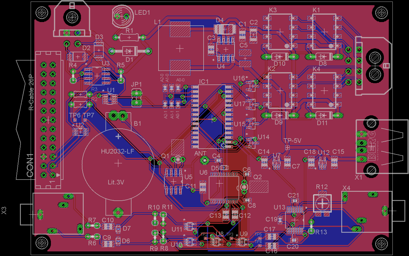
3 boards routed !
I managed to route all 3 boards ! Still some minor changes needed to the mainboard.
Special thanks to http://www.freerouting.net/ for doing the autorouting part. All routes where routed with this autorouter. Only a few routes where manually routed (especially around the FM receiver).
Mainboard:
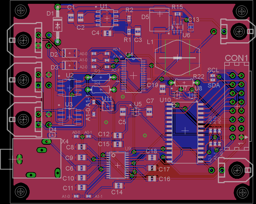
Displayboard:
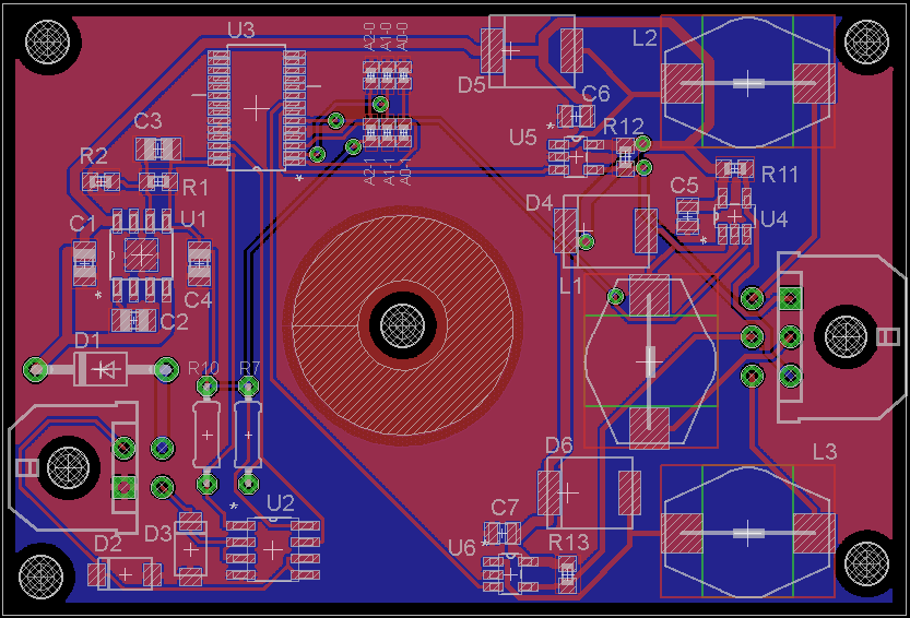
Leddriverboard:
Special thanks to http://www.freerouting.net/ for doing the autorouting part. All routes where routed with this autorouter. Only a few routes where manually routed (especially around the FM receiver).
Mainboard:
Friday, November 1, 2013
First draft of Mainboard, Displayboard and Leddriver board
Wednesday, October 23, 2013
First version of mainboard schematic
A first (draft) version of the mainboard schematic is available here:
https://rgb-clock.googlecode.com/svn/trunk/pcb/RGBClock/Mainboard.pdf
https://rgb-clock.googlecode.com/svn/trunk/pcb/RGBClock/Mainboard.pdf
Wednesday, October 9, 2013
Eagle library parts
I'm surprised to learn that creating Eagle library parts is actually quite easy; see this tutorial:
http://www.msilverman.me/2010/06/creating-a-new-device-in-eagle/
And it is even faster when you copy a existing symbol/package. In my case the library for the Si4735-D50 FM receiver...
http://www.msilverman.me/2010/06/creating-a-new-device-in-eagle/
And it is even faster when you copy a existing symbol/package. In my case the library for the Si4735-D50 FM receiver...
Monday, October 7, 2013
Schematics of PWM LED driver prototype board (PCA9685 and ZXLD1362 as main components)
I have uploaded the schematics of the PWM driver prototype board. It was just a test board to get started with Eagle software.
You can view the schema here. I'll start the schema entry of the other boards in the next days; all files will be available on the source page.
You can view the schema here. I'll start the schema entry of the other boards in the next days; all files will be available on the source page.
Subscribe to:
Posts (Atom)